
Installation · Auto-Coupling
Auto-Coupling System
Guide Rail Installation
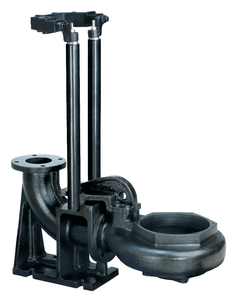
A guide rail system that connects a submersible pump to its discharge pipe, and releases it, just by lowering and lifting the pump on its chain. No flanges to unbolt, and no one has to enter the sump for maintenance or inspection. In eight sizes for 2” – 12” pipe.
- Pipe sizes
- 2” – 12”
- Sizes
- 8
- Sealed by
- The pump’s weight
- Bolts to undo
- None
What it’s for
Lift the Pump Out, Not the Pipework
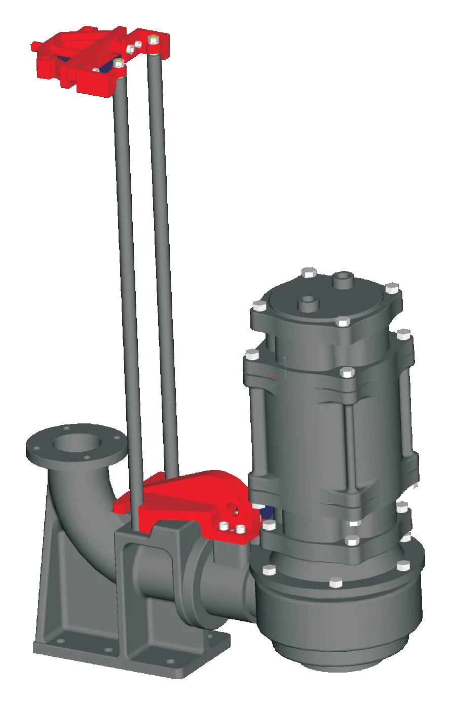
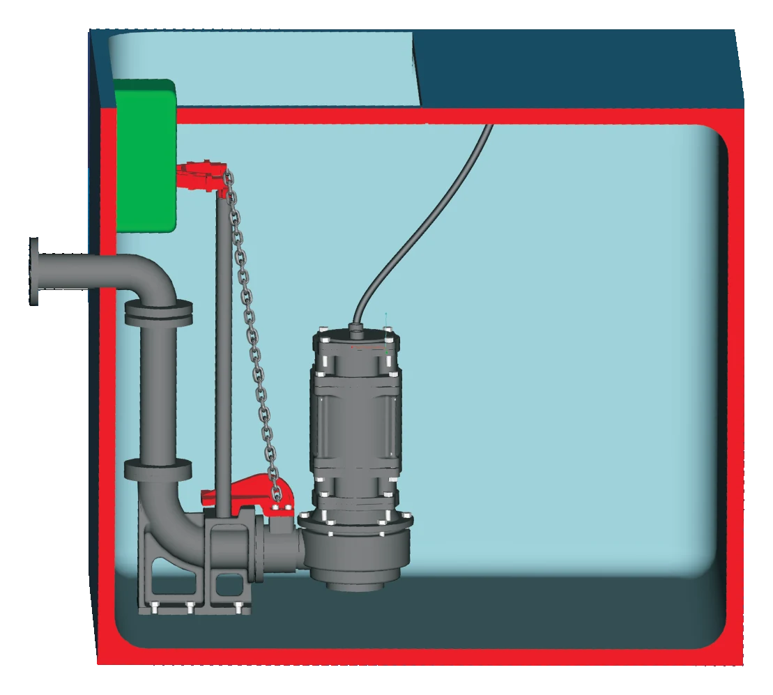
A submersible pump bolted straight to its discharge pipe has to be unbolted where it stands, at the bottom of the sump, every time it needs a look. Auto-coupling ends that. The bend pipe is fixed permanently on the sump floor; the pump runs down two guide rods on a guide hook at its discharge, and seats itself on the bend pipe as it is lowered.
Under the pump’s own weight, the locking arrangement and the inclined face of the bend pipe’s seat wedge tightly together and close on the sealing surface, so the joint doesn’t leak. Lift the pump on its chain and it separates from the seat on its own. It suits Point’s submersible sewage, drainage, cutter, grinder and chopper pumps — the PS, PDS and PCG among them.
Construction
How It’s Built
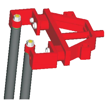
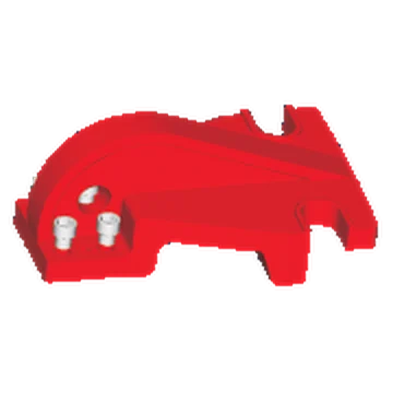
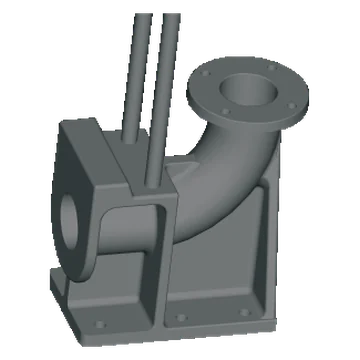
The guide rail system comes with three attachments; the two guide rods run between them.
Specifications
Technical Data
- Pipe sizes
- 2”, 2.5”, 3”, 4”, 6”, 8”, 10”, 12”
- Supplied with
- Fixing stand, locking arrangement, bend pipe
- Guide
- Two guide rods, from the fixing stand to the bend pipe
- Sealing
- By the pump’s own weight — no bolting
- Removal
- Lifted out on a chain, no sump entry
- Fixing stand
- Steel casting
- Locking arrangement
- Steel casting
- Bend pipe
- Cast iron
System
Materials
- 2” pipe
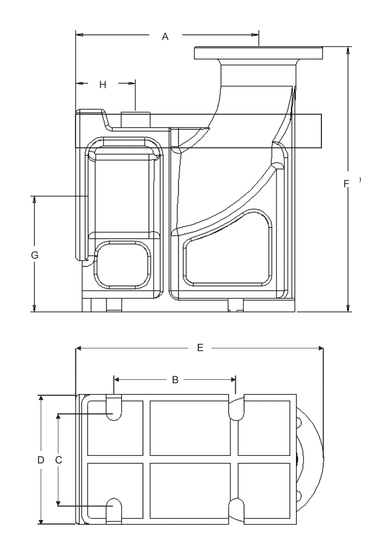
- A 97 · B 102 · C 104 · D 140 · E 184 · F 171 · G 100 · H 22
- 2.5” pipe
- A 295 · B 200 · C 165 · D 200 · E 290 · F 250 · G 165 · H 115
- 3” pipe
- A 356 · B 250 · C 203 · D 270 · E 390 · F 400 · G 200 · H 115
- 4” pipe
- A 350 · B 250 · C 203 · D 270 · E 390 · F 400 · G 200 · H 115
- 6” pipe
- A 395 · B 279 · C 254 · D 309 · E 390 · F 450 · G 250 · H 115
- 8” pipe
- A 425 · B 279 · C 254 · D 309 · E 381 · F 450 · G 257 · H 115
- 10” pipe
- A 476 · B 502 · C 254 · D 309 · E 628 · F 476 · G 254 · H 115
- 12” pipe
- A 552 · B 502 · C 502 · D 620 · E 651 · F 800 · G 500 · H 155
Dimensions in mm, A – H as on the drawing (for guidance and planning only)
Applications
Where It’s Specified
Raw sewage sumps and lifting stations, where the pump can be lifted out for a look without anyone going down. For sewage, cutter and grinder pumps.
Collection, equalization and transfer tanks in sewage and effluent treatment plants. See STP / ETP →
Drainage pits and basements, with a drainage pump that comes out for cleaning in minutes.
Storm water and large sewage pumping stations, where the high-discharge pumps are too heavy to unbolt in place. See industries we serve →
Common questions
Frequently Asked Questions
Does anyone have to go into the sump?
No. The pump is lifted out on its chain, guided by the rods, and comes away from the bend pipe on its own; lowered back, it seats itself again. Maintenance and inspection are done at the top.
How does it seal without bolts?
By the pump’s weight. As it comes down, the locking arrangement on its discharge and the inclined face of the bend pipe’s seat wedge tightly together and close on the sealing surface, so there’s no leak at the joint.
Which size do we need?
The one that matches the pump’s discharge — 2” to 12”. Tell us the pump and the depth of the sump, and we’ll confirm the size and the guide rods’ length.
What comes with it?
The fixing stand for the top of the sump, the locking arrangement for the pump’s discharge, and the bend pipe for the floor. The two guide rods run between the fixing stand and the bend pipe.